Direct drive air compressor motor selection is an equipment-integration task. The motor, airend, converter, cooling system, controls, and package structure must work at the same operating points. A direct connection can remove belts or a speed-changing gear from a particular layout, but it also fixes a closer relationship between motor speed and compressor speed. ENNENG’s archive identifies a TYDP direct-drive and gearless motor family and lists air compressors among public application directions. Those records establish a discussion area, not a finished selection for an unknown compressor.
Start with compressed-air demand and compressor type
Define the air system before sizing its motor. Record required flow, discharge pressure, pressure range, air quality, operating hours, ambient conditions, and the way demand changes through a normal shift or production cycle. Note whether the compressor operates continuously, cycles, unloads, or follows variable demand. The motor duty follows the compressor and control strategy; it cannot be inferred from a plant’s maximum air demand alone.
Identify the compressor technology and obtain the airend manufacturer’s permitted speed, torque, direction, lubrication, and thermal limits. Rotary screw, scroll, vane, and reciprocating machines do not present the same load pattern. A replacement project also needs the existing package’s performance data, controller history, alarm log, and maintenance record. These records help distinguish a motor problem from restrictions, poor controls, cooling faults, or system leakage.
The Compressed Air & Gas Institute’s Compressed Air Production handbook chapter shows belt, gear, and direct-coupled arrangements and notes that direct drive requires the drive and compressor to operate at the same speed. Use that statement as a system constraint, not as proof that direct drive is best in every case.
Build the motor duty from the airend map
Ask the compressor or airend supplier for the required shaft torque across the operating speed and pressure range. Include starting, unloaded running, loading transitions, full-load operation, turndown, shutdown, and any emergency sequence. If the package can restart against residual pressure, document how pressure is relieved and what condition the motor must overcome.
Do not select from a single rated-power point. Power, torque, and speed are related, but compressor losses and control states determine the actual shaft requirement. The proposal should show continuous and temporary motor capability against the required envelope. If minimum speed is limited by lubrication, cooling, or air quality, record that limit in the control specification rather than asking the motor to run indefinitely below it.
For an existing compressor, measured electrical input is not the same as airend shaft power. Fans, pumps, heaters, controls, and drive losses can sit inside the package boundary. CAGI’s Resource Library defines total package input power to include the compressor package auxiliaries and controls. Keep measurement boundaries consistent when comparing the old and proposed package.
Decide what “direct drive” means in the proposed package
Draw the mechanical chain. Show the motor shaft, coupling or shared shaft, airend, bearings, seals, support structure, and any retained transmission. The phrase direct drive is used for more than one physical arrangement. A flexible coupling between separate shafts creates different alignment and bearing responsibilities from an integrated rotor or common-shaft design.
State who controls axial and radial loads, how the shafts are located, and which supplier owns torsional analysis. Define coupling selection, balance grade, alignment tolerance, thermal growth, guard, and service access. If belts or gears are removed from an existing package, check whether they previously provided speed ratio, isolation, or a convenient maintenance boundary. Their removal changes more than the parts count.
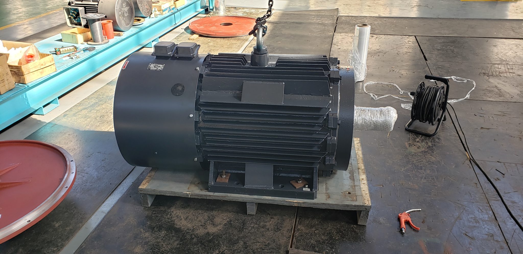
ENNENG’s TYDP family page is a starting point for discussing direct-drive configurations. The archived family material has project-specific limitations and does not justify applying one mounting, speed, voltage, or cooling arrangement across all products. Require a dimensioned interface drawing and an approved responsibility matrix for the offered package.
Coordinate the converter, controls, and protection
Specify supply voltage and frequency, converter location, cable length, network communications, and the compressor controller’s command structure. The drive must support the proposed permanent-magnet motor and the compressor’s operating sequence. Confirm the exact control mode, motor data required for tuning, feedback arrangement, current limits, and firmware. A successful bench rotation does not prove stable compressor control over the required pressure and speed range.
Define how the package handles start permission, load and unload commands, pressure control, anti-restart delays, emergency stop, and power recovery. Set alarm and trip behavior for motor temperature, bearing temperature where applicable, cooling loss, overspeed, overcurrent, phase or feedback faults, high discharge temperature, and airend protection. The compressor manufacturer should own process limits; the motor and drive suppliers should demonstrate that their controls respect them.
Review electrical protection, grounding, electromagnetic compatibility, and motor cable construction with the project engineer. If the converter is remote, include route and length in the RFQ. The U.S. Department of Energy Motor Systems material reinforces the need to treat the driven system, motor, and control as one performance boundary.
Prove cooling at the lowest continuous speed
Air compressor packages generate heat in the motor, airend, lubricant, cooler, and power electronics. Record inlet-air temperature, altitude, enclosure ventilation, dust, humidity, and recirculation risk. Define available cooling air or water and the package’s worst approved ambient condition. A motor that can generate low-speed torque still needs a verified path for rejecting its losses.
Ask for continuous-duty thermal capability at each required speed, not only at a rated point. A shaft-driven fan may move less air at reduced speed. Independent ventilation or another cooling method may be proposed, but its capacity, power supply, filtration, alarms, and maintenance access must be included in the package scope. The airend’s own lubrication and cooling limits can create a higher minimum operating speed than the motor’s electromagnetic limit.
During site testing, trend motor temperature, drive current, discharge temperature, ambient condition, speed, pressure, and package cooling state. Set a stabilization rule in advance. A short run on a cool day does not establish continuous service at the maximum specified ambient.
Compare performance using the same system boundary
Direct drive can remove transmission components in a defined arrangement, yet the result should be measured instead of assumed. Compare specific package performance at agreed pressure and flow conditions, including the power of auxiliaries that sit inside the selected boundary. Record inlet condition, pressure, demand state, and test method so the baseline and proposed package are comparable.
CAGI operates performance verification and provides education intended to support informed compressor selection. Its working with compressed air guidance emphasizes selecting the complete compressor system for the application. For procurement, request recognized package performance data where applicable and ask the compressor provider to explain test conditions and tolerances.
Keep maintenance claims equally specific. A direct arrangement may eliminate belt inspection or gearbox oil service if those components are truly absent. Bearings, seals, cooling equipment, filters, electrical connections, sensors, and converter components remain. Build the maintenance plan from the final bill of materials and manuals rather than from a general label.
Write a factory and site acceptance plan
The factory plan should cover the items that can be reproduced safely: documents, nameplates, winding and insulation checks, sensors, rotation, drive communication, protective functions, leak checks, vibration, and defined package performance points when the test facility can supply them. Record which values are measured, calculated, or declared. Tie each result to the serial-numbered equipment and software version.
Site commissioning should verify foundation, alignment, piping loads, electrical installation, cooling airflow, controls, interlocks, pressure settings, unload behavior, and operation across the permitted range. Trend the package during representative demand. If full production conditions are unavailable at startup, agree on a later witnessed performance period and retain responsibility for closing it.
Acceptance criteria need an owner and instrument. “Runs normally” is not a measurable result. Use agreed limits for pressure control, flow or process output, input power boundary, temperatures, vibration, noise where required, alarm actions, and stable operation. Store the final parameters and reports with the package documentation.
Prepare an RFQ that suppliers can answer
Send the air system profile, compressor and airend data, torque-speed requirement, pressure and flow range, supply, proposed drive, package layout, shaft and mounting drawings, cooling conditions, control sequence, protection needs, standards, test requirements, and site constraints. State whether the inquiry is for a motor, motor-drive set, integrated airend, or complete compressor package.
Ask each bidder to return a scope drawing, data sheet, capability envelope, cooling basis, responsibility matrix, test plan, assumptions, and exclusions. Compare the same equipment boundary. A lower motor-only price cannot be compared fairly with a package that includes the converter, coupling, cooling, controls, and testing.
ENNENG’s archived knowledge supports the existence of a direct-drive family, public air-compressor application direction, and project customization activity. It does not establish unlimited configuration availability or a guaranteed saving. Use the direct-drive selection guide to organize the evidence, then send the operating data for project review.
Evidence boundary
This article cites ENNENG knowledge records CAND-006 for the archived TYDP direct-drive and gearless family, CAND-008 for public application directions including air compressors, and CAND-010 for customization service. These candidate records do not prove a particular model, rating, delivery, or performance result. External context comes from CAGI’s Compressed Air Production, Resource Library, and Working With Compressed Air, plus the U.S. Department of Energy Motor Systems program. None of these sources certifies an ENNENG configuration.