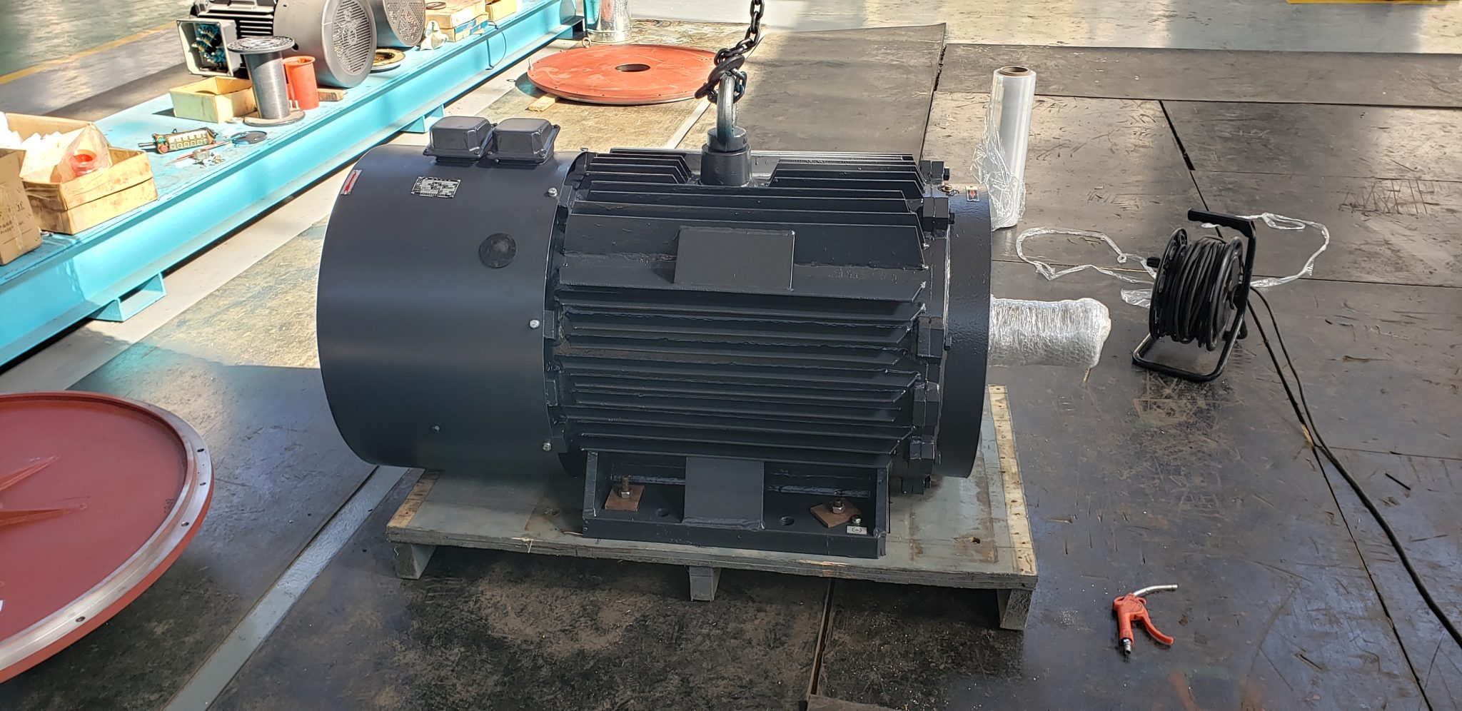
Direct drive motor maintenance removes gearbox and belt tasks from a drivetrain, but it does not remove the need for inspection, measurement, and documented limits. Bearings, cooling passages, electrical connections, sensors, the inverter, alignment, and the driven machine still determine reliability. A useful maintenance plan begins with the supplied manual and site risk assessment, then connects each inspection to a measurable condition. This guide shows how to build that plan without assuming that every direct-drive arrangement has the same construction or service interval.
Define the equipment boundary before writing tasks
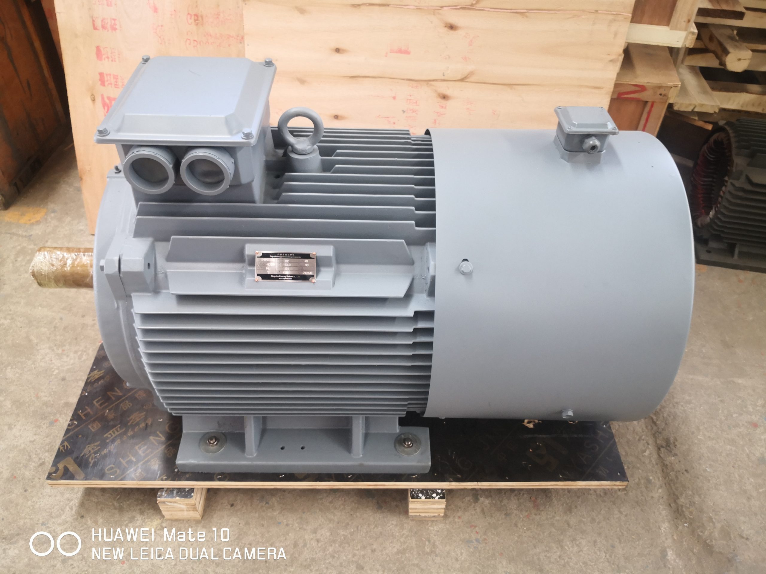
Start with an as-built asset list. Identify the motor, inverter, feedback device, cooling equipment, coupling or integrated shaft arrangement, bearings, seals, brake, sensors, cables, guards, and driven machine. Direct drive can mean a conventional motor coupled at process speed, a motor integrated around the machine shaft, or another gearless architecture. The accessible parts and service responsibilities differ, so a generic checklist must be reconciled with the actual drawings and manuals.
Assign ownership for each boundary. The motor supplier may define winding, bearing, and magnetic precautions; the inverter supplier defines capacitor, fan, filter, and firmware maintenance; the machine builder owns process-side loads and alignment; the plant owns isolation, access, and condition records. Put these roles in one maintenance matrix. The TYDP direct-drive overview provides ENNENG product-family context, while the controlled project documents must define the serviceable unit.
Establish a safe isolation and back-driving procedure
Permanent-magnet machines can generate voltage when the shaft turns. A disconnected inverter does not make a spinning motor electrically inactive. Before inspection, isolate all energy sources, prevent rotation from the process, verify zero energy according to site procedures, and consider stored energy in the drive DC bus, rotating mass, hydraulic head, gravity, or airflow. Only qualified personnel should perform electrical and mechanical work.
ABB's official direct drive cooling tower motor manual warns that rotating a permanent-magnet motor can induce voltage at its leads and gives equipment-specific inspection and lubrication instructions. It is a useful example of why the supplied manual governs. Do not copy its intervals or grease quantities to a different motor. Build the plant procedure from the exact model, mounting, atmosphere, and driven-machine hazards.
Create a clean baseline after commissioning
Record normal behavior while the system is healthy. Capture speed, motor current, torque estimate if available, winding and bearing temperatures, inverter temperature, vibration at defined locations, process output, cooling status, and ambient conditions. Save representative spectra or trends where condition monitoring is used. Photographs of cable entries, guards, drains, and sensor mounting can help identify later changes.
The baseline needs operating context. A vibration or temperature value means little without load, speed, product, and stabilization time. Record the drive firmware and parameter backup with the measurements. Note known resonances and restricted-speed bands. If the motor is integrated into the machine, include process-side bearings and structures in the measurement map so a change is not automatically blamed on the motor.
Inspect cooling, cleanliness, and enclosure integrity
Heat rejection depends on clear airflow or a healthy liquid-cooling circuit. Check external fins, air paths, filters, fans, heat exchangers, pumps, flow switches, hoses, and coolant condition as applicable. Confirm that guards, insulation, dust, oil, or process buildup has not blocked the designed path. Investigate why contamination appeared instead of treating cleaning as the only corrective action.
Inspect seals, gaskets, conduit entries, drain and breather arrangements, fasteners, and signs of moisture or corrosion. Verify space heaters or anti-condensation measures where specified. A washdown, dusty mine, humid tower, or outdoor installation needs a schedule based on exposure. The U.S. Department of Energy's equipment operations and maintenance summaries emphasize equipment-specific O&M and system performance. Use those summaries for program structure, then apply manufacturer instructions to the actual motor and drive.
Trend bearings, vibration, and mechanical loads
Direct drive may eliminate gearbox bearings and belt tension, yet motor and process bearings remain. Follow the supplied lubrication type, quantity, method, and interval. More grease is not automatically better. For sealed or non-regreasable bearings, do not add a fitting without engineering approval. Record lubricant lot and work performed so a later temperature change can be related to maintenance history.
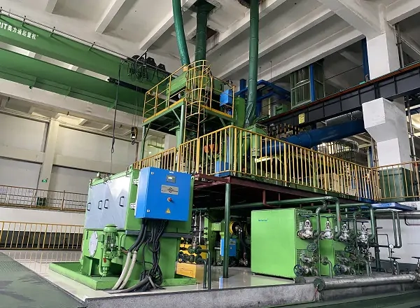
Trend vibration at consistent points and operating conditions. Evaluate changes in overall level, frequency content, axial versus radial direction, and speed dependence. Possible causes include imbalance, misalignment, looseness, bearing damage, rubbing, electrical excitation, structural resonance, or a process change. Check foundation bolts, fit, shaft runout where accessible, and driven-machine condition. A removed gearbox does not guarantee alignment or eliminate resonant behavior.
Check electrical connections, insulation, and sensors
Inspect terminals, cable glands, grounding and bonding, shield terminations, sensor connectors, and evidence of heating or moisture. Use torque values and test methods from the equipment documentation. Plan insulation-resistance or other winding tests with awareness of connected electronics; isolate or protect the inverter and sensors as instructed. Record temperature and test conditions so readings can be compared over time.
Verify winding and bearing temperature sensors, vibration transmitters, speed feedback, cooling switches, and protective relays. A sensor can remain electrically connected while drifting, losing contact with the measured surface, or being ignored by control logic. Test the complete chain from sensing to alarm or trip at the approved interval. Preserve alarm thresholds and delay settings with the drive parameter record.
Include the inverter and control system
The motor cannot be maintained independently from the controller that supplies it. Inspect inverter cooling, filters, fans, capacitors or other life-limited parts according to its maintenance schedule. Review fault history for recurring overcurrent, DC-bus, feedback, thermal, or communication events. Repeated resets without diagnosis can conceal a developing mechanical or electrical problem.
Back up parameters after approved changes and control who can edit them. Compare motor identification data, current limits, maximum speed, thermal inputs, and stop behavior against the commissioning baseline. Firmware changes and replacement drives require a compatibility and functional review. The low-speed high-torque sizing guide explains why torque, speed, cooling, and protection must remain linked throughout the asset life.
Set intervals from condition and consequence
Manufacturer intervals are the starting point. Adjust inspection frequency using operating hours, starts, load cycles, contamination, ambient temperature, criticality, and measured condition. A continuously loaded production asset and a clean standby machine should not automatically share the same calendar. Shorten intervals when trends change or exposure increases; extend only through a controlled reliability review with enough evidence.
Define trigger levels and actions before alarms occur. For each measurement, state what change prompts recheck, planned intervention, or immediate shutdown. Combine time-based work with condition monitoring where it adds value. Keep the plan concise enough to execute and detailed enough to reproduce. A large checklist that technicians cannot finish or interpret is weaker than a smaller set of well-defined measurements with clear ownership.
Build a maintenance record that supports decisions
Every record should identify the asset, date, running condition, technician, instrument, result, action, parts, and post-work verification. Attach trends rather than only the latest number. When work changes alignment, bearings, sensors, cooling, cables, drive parameters, or firmware, update the as-built package and establish a new baseline if needed.
ENNENG's archived sources support knowledge references ENNENG-CAND-006 for the TYDP direct-drive and gearless family, ENNENG-CAND-008 for listed industrial application directions, and ENNENG-CAND-010 for a stated customization service. They do not prove a universal maintenance interval, “maintenance-free” operation, or suitability for every environment. Use the engineering selection guide and contact form to request the manual, spare-parts boundary, and service data for a proposed configuration.
Evidence boundary
The maintenance principles above use official ABB equipment documentation and DOE O&M resources as general references. ABB instructions apply to the cited ABB product and illustrate the need for model-specific procedures; they are not instructions for an ENNENG unit. ENNENG candidate records establish only product and business context. The supplied manual, project drawings, risk assessment, plant isolation rules, and recorded operating condition govern the actual maintenance plan.