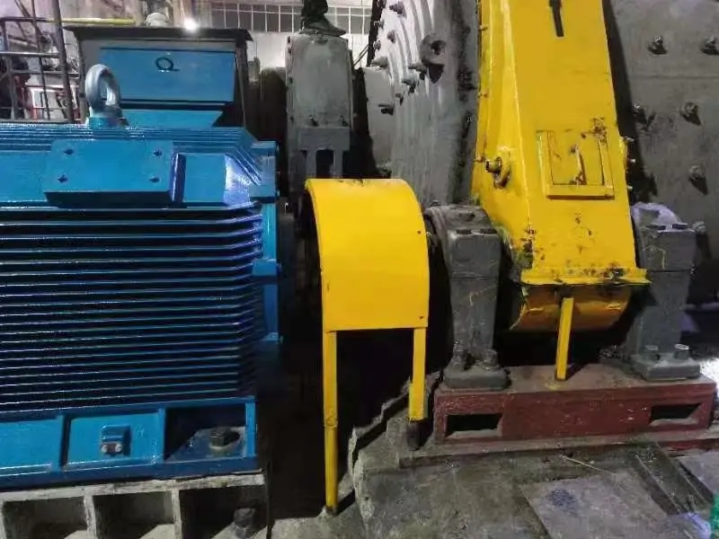
A ball mill direct drive retrofit starts at the mill, not at a motor catalogue. The existing transmission may contain a motor, couplings, reducer, pinion and girth gear; removing one element changes torque paths, support duties and control behavior elsewhere. ENNENG's archived product material identifies a TYDP direct-drive and gearless motor family, and its application material discusses ball mills. Neither source, on its own, establishes that a specific mill can use a standard configuration or achieve a particular saving. This guide sets out the evidence a plant team should collect before deciding whether a low-speed permanent magnet drive is worth engineering in detail.
Begin with the as-built drivetrain
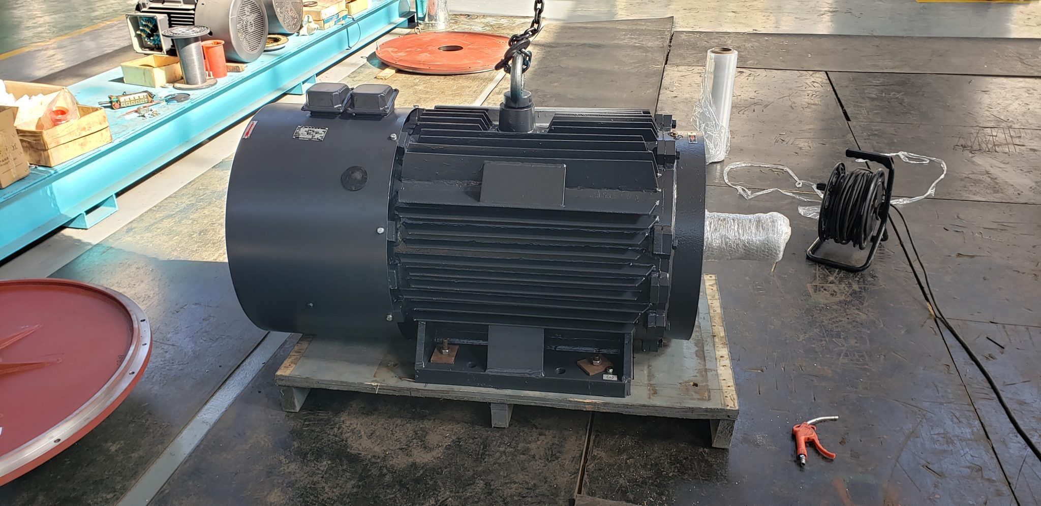
Walk the machine before drawing the proposed arrangement. Record the motor and gearbox nameplates, ratio, coupling types, pinion and gear condition, bearing locations, foundation geometry, guarding, lubrication services and access for lifting. A drawing issued years ago may omit field modifications. Measure the actual shaft centerlines and clearances; photograph identification plates and interfaces with a scale reference. Ask maintenance staff where vibration, heat and oil leaks occur, but distinguish observations from measured trends. If the existing gearbox supports a shaft or creates a necessary offset, its removal leaves a structural function to replace.
ABB's published gearless mill drive is a ring-motor architecture in which the mill body becomes the rotor. That is a specific system design, not a synonym for every permanent magnet motor connected directly to a mill. An ENNENG TYDP concept might use a different mechanical boundary. Put both concepts on a one-line mechanical diagram before comparing them. The diagram should show precisely which gearing, shafts, bearings and couplings remain. The direct-drive versus gearbox comparison explains why this boundary controls the economics and maintenance assessment.
Record the mill's duty, including difficult starts
Rated running power is only one point. The engineering team needs mill speed across the operating range, normal and maximum charge, breakaway behavior, acceleration time, planned stops, emergency stops, inching or positioning requirements and any reversing operation. Determine whether a charged mill can sit idle long enough for material to settle. A restart after an extended stop can be unlike a routine start. Log drive current, speed and process state during representative cycles where instruments and site procedures allow it. If starting torque is inferred from a model rather than measured, retain the assumption and uncertainty in the record.
The existing motor rating should not simply be divided by gearbox ratio and treated as the new motor rating. Transmission losses, overload allowances, inertia and process variation all matter. At the driven shaft, torque equals power divided by angular speed, so a low-speed design can impose a large continuous torque requirement even when its power seems familiar. Our low-speed high-torque sizing guide covers the inputs needed to turn the duty into a motor envelope. No article can substitute for a project calculation using the actual mill and charge.
Check the structure before choosing an electromagnetic design
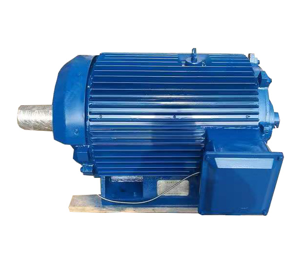
A motor can make the required torque and still be a poor retrofit. Identify where radial and axial loads travel, who owns the driven-shaft bearings, how torque reaction reaches the civil structure and whether the new arrangement changes dynamic behavior. Review baseplate stiffness, anchor bolts, grouting, alignment tolerance and thermal growth with the machine designer. A gearbox housing sometimes provides convenient stiffness and alignment points; its removal can make an apparently shorter drivetrain harder to support. The cable route, converter room, cooling water or air route and maintenance access also belong on the layout.
If the proposal changes the mill shell or its bearing arrangement, involve the mill OEM or a qualified mechanical specialist. Avoid accepting a rendering as proof of fit. Obtain a dimensioned general arrangement drawing and an interface responsibility matrix. The latter should identify who designs the coupling, guarding, support steel, foundation changes and instrumentation. For a live plant, the installation sequence matters almost as much as the final drawing. A lifting plan, survey hold points and a realistic rollback option reduce the chance that one unknown shaft dimension extends the outage.
Treat motor, converter and cooling as one system
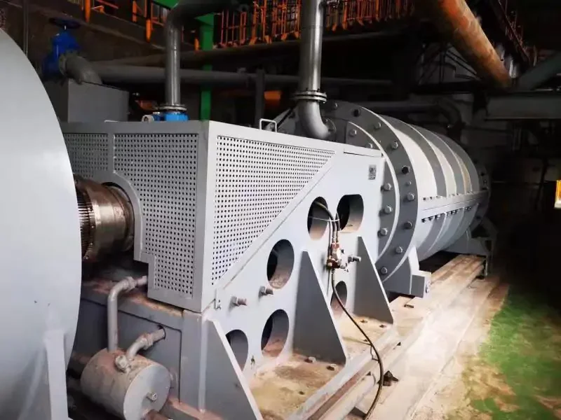
Low-speed torque is produced through the electrical drive system, not by the motor alone. Specify supply voltage, converter topology, cable distance, harmonic or power-quality constraints, protection coordination and the control modes used during starting, positioning and loaded operation. The motor's continuous torque curve must be tied to ambient conditions and a stated cooling method. A shaft fan that works at higher speed may have little airflow when the mill turns slowly; whether independent cooling is needed is a design question, not a default answer.
Ask the supplier to identify current and temperature limits at each operating point, overload duration, feedback arrangement and what happens after a sensor or cooling fault. The drive should be commissioned with agreed ramp and torque limits so operators can recognize an abnormal load before a protective trip. ABB lists frozen-charge detection, controlled rollback and positioning functions for its own gearless mill system. Those are useful examples of control questions to ask. They must not be read as claims that ENNENG's proposed package includes the same functions.
Define a fair energy and maintenance comparison
Direct drive can remove mechanical loss and service points, but it can also add converter, cooling and electrical maintenance. Compare input energy for the same quantity and quality of processed material, within a documented production window. Record ore or feed changes, charge, throughput, ambient conditions and operating hours. Decide whether the baseline includes the existing converter, lubrication auxiliaries and cooling loads. After commissioning, measure the proposed system at the same boundary and label adjustments. The US Department of Energy treats motor efficiency as a motor-system issue, which is the right frame here.
Do not borrow savings percentages from an unrelated mill. ENNENG's old application page contains a broad saving claim for a ball-mill modification, but the captured material does not give the site-specific baseline and measurement method needed to transfer that number to a new project. Calculate energy, maintenance labor and outage effects separately. Likewise, a claim of almost maintenance-free operation on a product page should be translated into a list of removed tasks and retained tasks. Bearings, cooling, sensors, drive electronics, cables and structural connections still require inspection.
Agree on acceptance before the purchase order
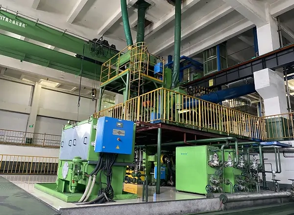
Write an acceptance matrix around the real duty. A factory test may verify winding, insulation, protection, temperature sensors and a portion of control behavior; it cannot reproduce every loaded mill condition. Site commissioning should include rotation checks, alignment, interlocks, low-speed control, start and stop sequences, steady operation and any specified abnormal condition that can be tested safely. Name the measurement instruments, stabilization period and pass criteria. State who signs off the mechanical, electrical, process and safety portions.
A useful matrix separates a demonstrated result from a calculation and from a supplier declaration. Record the test speed, torque or process proxy, input power, temperature, vibration, cooling state and alarm behavior. If a target cannot be demonstrated during initial commissioning because the process cannot reach that condition, define a later witnessed test. Version the settings and drawings supplied at handover. Otherwise, an operator may face an unexplained trip months later with no record of the accepted tuning.
Build a decision-ready RFQ package
Send an as-built drivetrain diagram, mill and charge description, speed and torque envelope, nameplate photos, shaft and foundation drawings, electrical single-line diagram, cooling utilities, control requirements, operating log and shutdown window. Identify missing measurements explicitly. Ask vendors to return a proposed architecture drawing, scope boundary, performance basis, exclusions, test plan and responsibilities for integration. Invite alternatives if the data indicate that retaining a geared arrangement would be more practical. A credible RFQ should make that comparison possible.
ENNENG's TYDP family page is a starting point for a product discussion, while the retrofit input guide helps organize the project data. The archived ENNENG ball-mill pages provide application context, not proof of a selected motor rating or savings for your mill. Send the measured envelope and drawings through the engineering inquiry form for configuration review. Keep procurement and publication decisions open until the technical reviewer and plant team can verify the final claims.
Technical references and evidence boundary
- ABB Gearless Mill Drives describes ABB's ring-motor architecture and control functions. Its design is distinct from an unverified ENNENG proposal.
- US Department of Energy Motor Systems provides guidance and tools for motor-system energy assessment.
- ENNENG knowledge archive: ENNENG-SRC-FA10C0DAACC73B5A100C, TYDP Series Direct Drive and Gearless Motor; ENNENG-SRC-93D317FE44C388148849, Ball mill of Gold Mine; ENNENG-SRC-B458F18153D7715F4E32, PMSM For Gold Mine Ball Mill. These are company-source records, not independent verification of performance.
Bring the operating data to the discussion.
Selection depends on the actual load, drivetrain and site constraints. Share your measurements and drawings for a project-specific review.