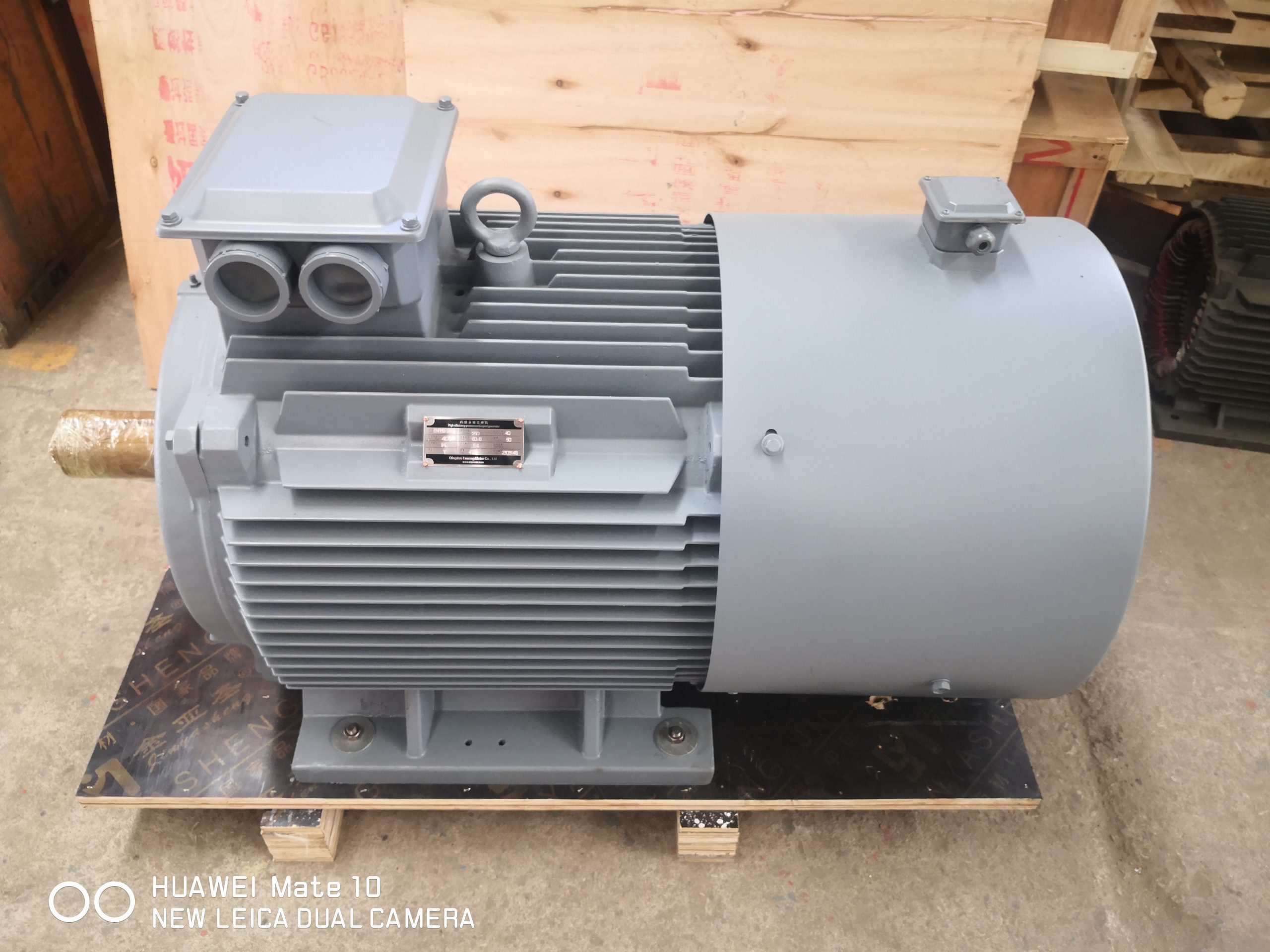
Direct drive motor cooling begins with a slightly awkward sketch. In an illustrative design review, a red arrow follows heat from the winding to the frame, then stops. Nobody has drawn the last step into air or water. Yet the proposed motor is expected to make high torque near process speed, exactly where a shaft fan may be least helpful.
Removing a gearbox changed the drivetrain. Heat still needs an exit. The red marker stays on the table until that exit has a name and an owner.
Find the awkward part of the cycle
The duty sheet looks nothing like a catalog row. Long black blocks show where torque must persist. Peaks stick up between them. Near the end is a slow, stubborn stretch that lasts longer than expected. Starts and stops are scribbled in the margin, along with reversal, dwell, and the chance that the load may drive the shaft.
A second sketch shows the room. The motor sits high, close to a hot duct, with dusty air moving poorly around one end. Altitude, moisture, enclosure, and orientation are added. Equal shaft power does not guarantee equal heat: speed and current shift it, as do harmonics, load, and the coolant path.
Unknown duty stays unknown. It becomes a measurement job rather than an excuse for a larger frame. The low-speed high-torque product page gives the team a place to collect those inputs.
A shaft fan follows speed, not torque
At rated speed, the fan looks busy. At a slow process point, it doesn't. The motor may still carry serious torque there, which is why the rated-speed line cannot quietly stand in for low-speed continuous capability.
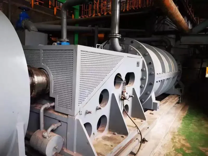
The supplier is asked for a curve with cooling conditions attached. How much torque can remain continuously at each required speed? Was that established by test, calculation, or both? A note under the curve should reveal its assumptions. Perhaps it belongs to one converter and one inlet temperature. Perhaps operation below a certain speed needs a time limit or another cooler. Those conditions become control rules.
Sometimes the shaft fan is enough. A duty that touches low speed briefly may have enough thermal margin. But the reason needs to appear in the evidence. “Direct drive” is not a cooling method.
A separate blower earns a row in the system list
The next sketch adds an independently powered fan. Airflow no longer falls with shaft speed. Good. Now a new set of questions arrives.
The designer walks upstream from the blower. The inlet is warmer than room air. A filter and two bends sit before it; a guard sits after it. Suddenly the catalog airflow is not the installed airflow. Can hot discharge return to the inlet? Who supplies the starter and power? A flow switch without a control response is merely an observer.
The maintenance lead circles the filter. Can someone reach it? How often will a dirty process load it? If the air is wet or corrosive, drainage and material choices enter the drawing. The factory may use a temporary open blower for the run. Its result is kept, but the report does not pretend that the final filtered duct was present.
A water jacket moves heat and responsibility
The liquid-cooled sketch is compact. It also reaches beyond the motor. Soon the simple jacket has company: a pump and exchanger, pipework, valves, a strainer, two instruments, a drain, and a plan for leaks. Site utilities have entered the design.
ABB's 2026 permanent magnet motor series announcement describes water-jacket cooling for ABB's cited platform. It shows what this architecture can look like. It says nothing about an ENNENG rating.
The proposed machine gets its own water-side sheet. Coolant and inlet temperature come first; flow, pressure drop, chemistry, connection, freezing, and condensation follow. Someone closes an imaginary valve with the marker. Now the controls team must say what the drive will do. Alarm, torque reduction, stop, and restart rules have to be named.
Air locks and reversed connections are ordinary mistakes. Fouling is slower but just as real. The commissioning sheet therefore includes filling, venting, flushing, flow proof, and the heat exchanger's actual duty.
The IC code is the start of a drawing
The chosen cooling route is checked against IEC 60034-6, which defines IC designations and classifies coolant circuits and movement. The code is written down. The drawing is not finished yet. A designation by itself does not show flow, cooler construction, redundancy, monitoring, or which connection belongs to the plant.
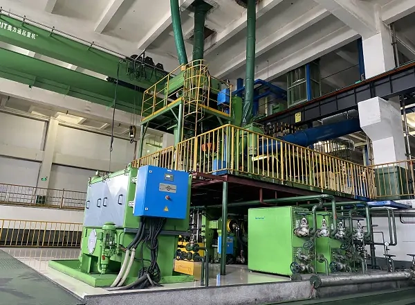
Arrows now show primary and secondary coolant paths. Fans, pumps, exchanger, filter, temperature points, flow or pressure devices, and the supply boundary get labels. Auxiliary electrical load is added too. Otherwise the system-efficiency comparison will lose part of the system.
For rating and performance, the file points to the current IEC 60034-1:2026 where its scope fits the machine. The purchase specification names the edition and applicable requirements. “IEC cooling” would tell the buyer very little.
Installation can erase a good thermal design
The layout drawing reaches the meeting table. A platform sits close to one air inlet. A guard blocks access to a blower. A pipe would need to cross the terminal box. On paper, moving the platform costs an eraser stroke. On site it would cost steelwork and delay.
The layout is therefore walked around: fins, inlets, outlet air, fan removal, pipes, terminals, and inspection points. Turn the machine vertical and drains or trapped air may behave differently; bearings and access may change too. Move it outdoors and the sketch acquires sun, rain, condensation, chemicals, debris, and wind.
The manufacturer should publish the restrictions that preserve the offered rating. Those restrictions are checked while steel and cable tray can still move. If servicing a small motor requires dismantling the surrounding plant, its compact frame has not saved much space.
The heat map carries the drive's signature
A PM direct-drive motor rarely works alone. Change the switching or current waveform and its loss can move. Cable and filter matter; so do control mode, feedback, field weakening, and current limits. Motor and drive data are pinned to the same board.
The thermal file identifies the converter and settings behind each result. Continuous and peak current limits sit beside the speed range. So do any deratings. A different site drive may still be suitable, but it needs an accepted comparison rather than a casual substitution.
ABB's direct drive motor portfolio shows application-specific motor and matched-drive arrangements. That supports the system view. It does not establish compatibility between ENNENG and an unspecified converter.
A temperature sensor needs a verb
“Monitor” is not enough. The review takes each device and adds an action. Winding temperature rises: warn, reduce load, or stop? Bearing temperature changes: how fast, and who sees it? Coolant flow falls: what delay is safe? A leak switch opens: may the motor restart automatically?
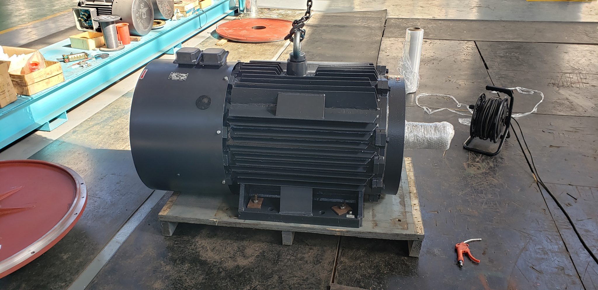
Signal type, range, wiring, alarm, trip, delay, and controller are written beside the sensor location. Inlet and outlet coolant temperatures may be useful. So may airflow, pressure, or flow. The thermal model explains how these measured points protect internal parts that have no sensor.
This prevents one cool reading from becoming proof that the end winding, magnet, bearing, and every hidden hot spot are also cool. The sensor is evidence only inside the design that interprets it.
Compare the installed cooling package, not the motor alone
Three columns go on the procurement sheet. Column one is the shaft fan: low-speed limit and cleaning access. Column two is the external blower, followed by its filter, power, duct, interlock, noise, and spare. Column three starts with a water jacket and quickly fills with pump, exchanger, valves, fluid care, drainage, leaks, and cold-weather work.
Procurement adds the costs that a motor price misses. Auxiliary power, maintenance time, outage exposure, floor and service space, noise, room heat, water, and commissioning fill the next rows. Real project values replace generic savings claims. An unknown remains blank instead of receiving a convenient estimate.
The bottom row contains names. One for design, another for supply and installation, then power, controls, test, and maintenance. This responsibility matrix is plain. It is also the difference between a cooler on a drawing and a cooling system that can run.
The test must visit a representative thermal corner
The witness sheet fixes the thermal scene: speed and torque, time, inlet condition, flow and pressure, test drive, sensor points, instruments, and the moment called stable. A no-load spin is still useful for direction, switches, sensors, pumps, and leaks. Low-speed loaded heat remains unproven until an appropriate duty is applied.
When the facility cannot reproduce the full process cycle, the evidence is divided openly: thermal calculation here, component record there, partial-load run, then installed verification. Nothing is promoted to a full-duty test by changing the report title.
At site, the team checks clearances, piping or ducts, utility quality, signals, alarms, trips, and temperature as load comes on. The baseline flows into the direct drive motor maintenance plan.
Evidence boundary
ENNENG-CAND-006 supports the historical existence of a TYDP direct-drive and gearless family. Two more archive entries have narrow uses. CAND-008 records old application directions and CAND-010 a past customization statement. Neither can fill in today's cooler, rating, certificate, or application approval.
IEC and ABB provide general cooling and system context. ABB's claims remain ABB's. Buyers can review the TYDP series context and send the duty, drive, environment, and available utilities. Approval rests on the offered data sheet, thermal work, interfaces, protection schedule, and agreed tests.