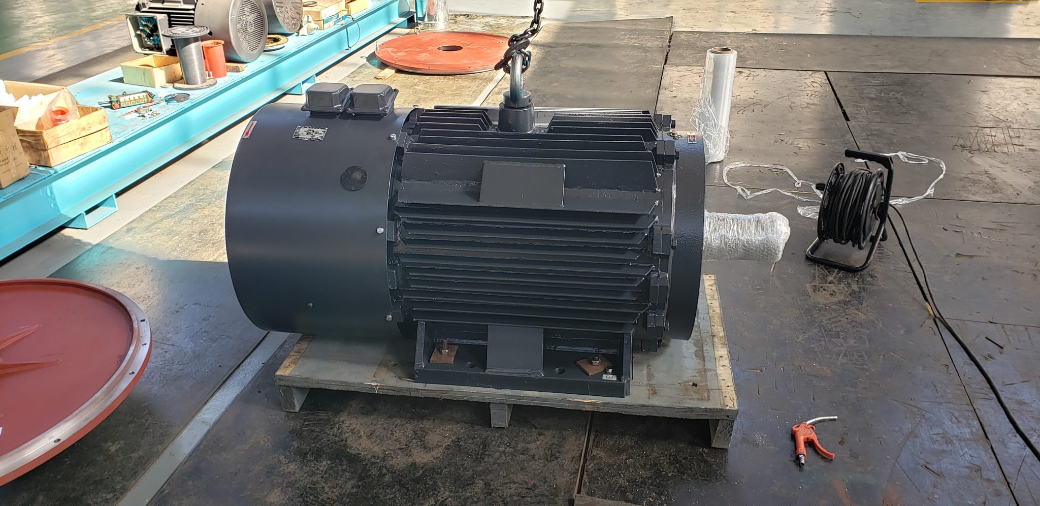
Direct drive motor retrofit planning begins with a measurement problem, not a motor catalog. Removing a gearbox, belt set, or other transmission changes speed matching, torque, inertia, bearing loads, alignment, structure, controls, protection, and maintenance boundaries. A successful project defines the existing system and its process output first, then designs the motor, inverter, mechanics, and acceptance test as one package. The following checklist is intended for industrial engineers preparing a gearless conversion.
Confirm why the retrofit is being considered
Write the problem statement in operational terms. Examples include repeated gearbox maintenance, belt replacement, poor speed control, unavailable spares, excessive noise, a process-capacity change, or an energy study. Record frequency, downtime, repair history, and production impact. Avoid beginning with a promised savings percentage. The project may still be justified by reliability, controllability, or lifecycle risk even when energy savings are small.
Define the success criteria before soliciting equipment. State required throughput, speed range, availability target, maintenance tasks to be removed, acceptable outage, and the measurement method for energy or performance. If the existing train has a fault, decide whether the retrofit should correct its root cause. A misaligned foundation, unstable process, poor lubrication practice, or overloaded machine can damage a new direct-drive system as readily as the old transmission.
Measure the existing operating envelope
Collect shaft speed, electrical input, process output, and operating hours at representative production states. Estimate or measure torque with a documented method. Record starts, acceleration, reversals, braking, jams, and transient peaks. A gearbox ratio converts motor speed and torque; once it is removed, the new motor must meet process-shaft torque directly across the full duty rather than merely match the old motor's nameplate power.
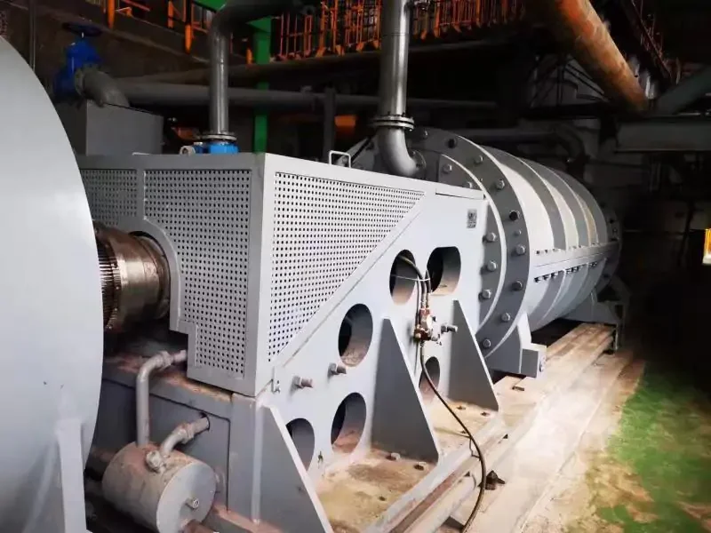
Keep raw data and uncertainty. Electrical input alone does not reveal shaft torque unless losses and power factor are handled appropriately. Nameplate values do not prove actual load. The U.S. Department of Energy's motor and drive system sourcebook recommends evaluating the complete motor-driven system and actual load. Use that method to build a baseline that can later support a defensible before-and-after comparison.
Recalculate speed, torque, and inertia at the process shaft
Create a torque-speed-time table at the driven shaft. Include continuous duty, short peaks, acceleration torque, and maximum back-driving speed. Calculate reflected inertia for the old arrangement and model the new coupled system. Removing a ratio changes what the motor and inverter see during acceleration and disturbance. Confirm whether the process needs holding torque, controlled crawl, or operation through a resonant speed.
Request continuous and peak torque-speed curves for the proposed motor-drive combination. Put every measured point and transient on those curves. State ambient, cooling, and cycle assumptions. A large low-speed motor may need different cooling and may impose a different electrical current profile from a higher-speed motor with a reducer. The low-speed high-torque motor sizing guide provides a detailed input list for this step.
Redesign the mechanical interface
Survey the installation as built. Measure shaft diameter and length, key or spline, centerline, mounting faces, bolt pattern, runout, axial position, available envelope, guards, lifting route, and service clearances. Record process-side radial and axial loads. If the new motor connects directly to the machine shaft, define which bearings locate the rotor and which accept thrust. Do not let both suppliers assume the other party owns shaft support.
Check foundation stiffness, natural frequencies, alignment method, thermal growth, and torque reaction. A gearbox may have served as a structural element or allowed offsets that the new arrangement cannot tolerate. Use a dimensioned interface drawing and tolerance stack. ABB's official direct drive motor overview illustrates how a gearless design removes belts and gearboxes in one application family. It supports the architectural concept, while the project drawing must establish the actual fit and loads.
Review the electrical supply and converter
Specify incoming voltage, fault level, transformer constraints, harmonics requirements, cable route, and available switchgear. Select the inverter with the motor and duty. Confirm continuous and peak current after derating for enclosure, ambient, altitude, and switching frequency. Review motor insulation, cable length, filters, grounding, electromagnetic compatibility, and bearing-current mitigation.
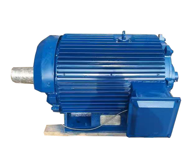
Define regenerative states. A descending load, high-inertia deceleration, process overrun, or fluid flow can drive the motor and raise the DC-bus voltage. Decide whether the system coasts, uses a brake chopper, regenerates to the supply, or applies another controlled response. Permanent magnets can generate voltage while turning, so isolation and maintenance procedures must address rotation even when the inverter is off.
Integrate controls and protective functions
Map every old signal and every new requirement. Include speed reference, run permission, emergency stop, process interlocks, cooling proof, feedback, winding and bearing temperatures, vibration where used, and communication with the plant control system. Define operating modes for commissioning, local maintenance, normal production, and degraded operation. Avoid carrying forward obsolete gearbox alarms without deciding what now detects the corresponding risk.
Protection settings should link to the approved torque-speed and thermal envelope. Define current limit, overload duration, stall, overspeed, feedback loss, overtemperature, cooling loss, vibration, and communication failure. Record the required response and reset authority. The direct-drive versus gearbox guide can help teams compare system boundaries before finalizing which components and failure modes the retrofit actually removes.
Plan installation and outage work in detail
Develop a removal and installation method with verified weights, lifting points, access, temporary supports, isolation, and sequence. Check whether the old gearbox base can be reused, modified, or must be replaced. Plan machining, grouting, shimming, cable work, cooling connections, alignment, and guard fabrication. Identify hold points for dimensional inspection before irreversible work proceeds.
Prepare contingency paths for discoveries such as damaged shafts, inaccurate drawings, corroded foundations, or inaccessible fasteners. Confirm long-lead spares and site tools. Train the installation and operations teams on permanent-magnet hazards, new isolation rules, and changed maintenance tasks. A retrofit schedule based only on motor delivery can miss the field work that controls the actual outage.
Define factory and site acceptance evidence
The factory plan should list document review, electrical tests, sensor checks, rotation or run tests, balance or vibration evidence, and any agreed load points. State instruments, tolerances, temperature conditions, and records. If the supplier cannot reproduce full process load, identify which calculations or component tests cover the gap and which items move to site acceptance.
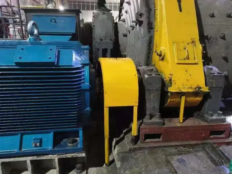
At site, verify alignment, wiring, grounding, cooling, feedback, guards, parameters, and interlocks before loaded operation. Progress through low-speed rotation, controlled acceleration, representative load, thermal stabilization, and transient events. Compare process output and energy only at matched production conditions. Keep the existing baseline, final drive parameters, trends, and sign-off together so the project outcome remains auditable.
Compare lifecycle scope rather than equipment price
Build a comparison that includes motor, inverter, cooling, mechanical adaptation, structure, cables, controls, installation, outage, commissioning, spares, and training. Credit removed gearbox oil, inspections, belt work, and related downtime only when those tasks truly disappear. Add new tasks for the inverter, sensors, cooling, and motor bearings. Use scenario ranges for uncertain energy prices, duty, or maintenance events rather than one guaranteed payback claim.
ENNENG's archived sources support ENNENG-CAND-006 for the TYDP direct-drive and gearless family, ENNENG-CAND-008 for listed application directions, and ENNENG-CAND-010 for a stated tailored replacement service. These candidates do not prove that every gearbox can be removed or that a fixed saving will result. Review the direct-drive product context, then send measured duty and drawings for a configuration discussion.
Evidence boundary
This article uses DOE system-level guidance and ABB's official direct-drive product explanation for general context. It does not transfer ABB performance claims to ENNENG equipment. Company-source records are limited to the existence of a direct-drive family, published application directions, and a stated customization service. A retrofit decision requires approved calculations, interface drawings, risk review, supplier manuals, and witnessed acceptance results for the exact installation.