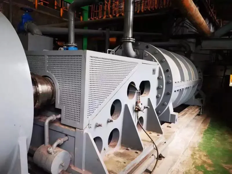
A direct drive permanent magnet motor turns at or near process speed; no gearbox creates the final ratio. That's the short definition. On a design sketch, the better definition is drawn in three arrows: the motor makes torque at driven speed, the inverter controls that torque, and the machine structure carries it into the process.
The pages below explain the idea through common layouts and duties. They don't report a customer result, and they don't put a red cross through every gearbox.
Direct drive describes the drivetrain, not one motor shape
Three sketches can all deserve the name. In the first, a low-speed PM motor connects to the process shaft through a coupling. In the second, a flange-mounted motor replaces a right-angle gearbox. In the third, the rotor and stator are integrated around part of the driven machine.
Those layouts don't share one bearing concept. They don't share one service plan either. A coupled motor can arrive as a more recognizable unit. A flange-mounted design may take torque reaction through the machine structure. An integrated design can reduce components but tie motor service more closely to the process equipment.
ABB's direct-drive motor page shows synchronous PM machines used in cooling-tower arrangements that can remove items such as gearbox, drive shaft, coupling, or belts. The example demonstrates an architecture. It does not define an ENNENG package or prove fit for another machine.
Permanent magnets establish the rotor field
Open the electromagnetic sketch. Magnets establish the rotor field. Around them, inverter-controlled stator current creates a rotating field and the requested torque. In normal controlled operation, the rotor follows that commanded field synchronously.
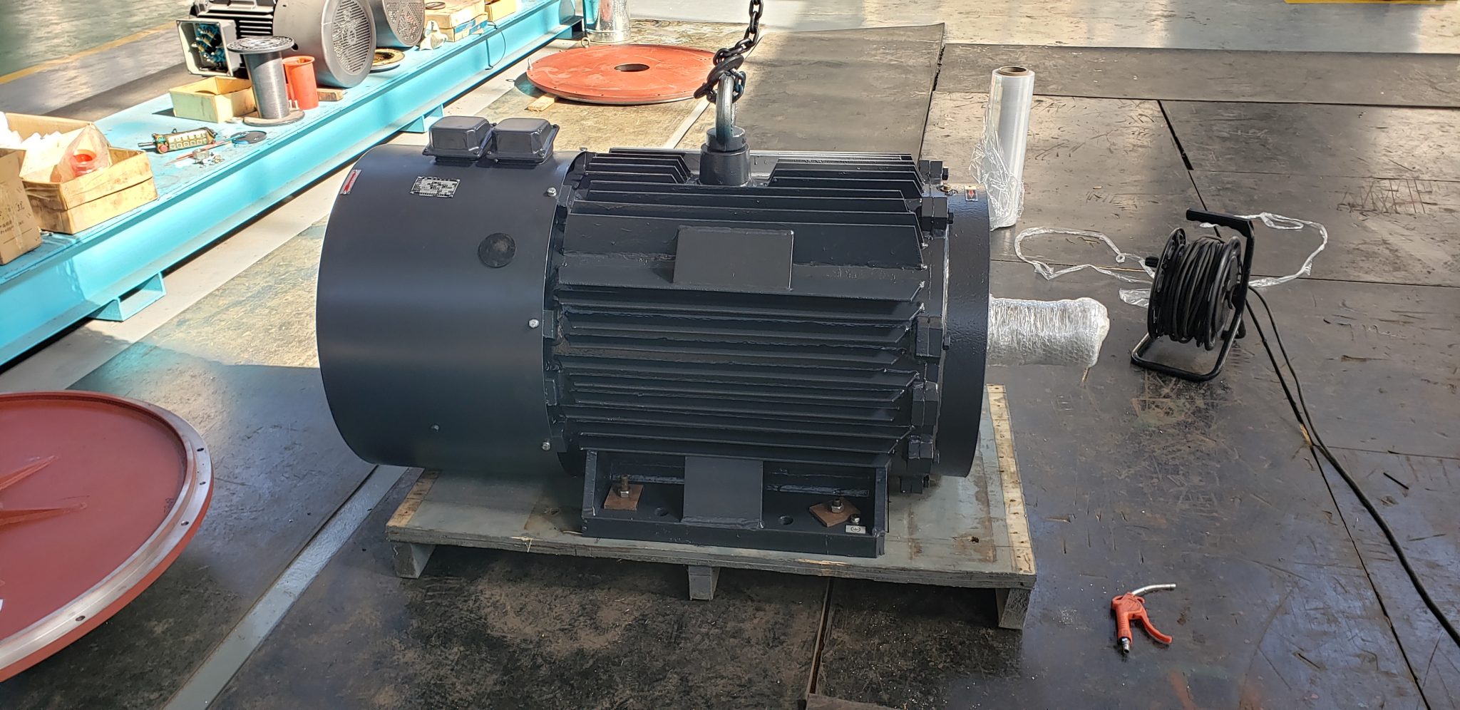
No wound-field excitation circuit has to feed the rotor in the same way. That difference matters inside the machine; it doesn't make the inverter, cooler, protection, or commissioning disappear. The offered winding and chosen drive still meet as one controlled pair.
ABB discusses PM synchronous motors within its Direct Torque Control platform. That source supports the relationship between motor topology and control method for ABB equipment. It cannot be used as a compatibility statement for an unspecified motor and drive from different suppliers.
High torque at low speed changes physical proportions
Power alone hides the problem. Move the same power to lower speed and torque rises. With a gearbox, a smaller fast motor makes that trade mechanically. Without the ratio, the electromagnetic design has to meet process torque itself.
The drawing often grows sideways. Air-gap diameter or pole count changes; material, shaft, and rotor support can follow. Heat needs another exit too. A resulting motor might be short and wide, with a water jacket or independent blower selected from its loss map.
So the old kilowatt plate cannot be converted straight into a frame. The process needs its own envelope. On the low-speed high-torque sizing guide, continuous points sit apart from peaks, starts, inertia, braking, reversal, and the ugly upset case.
Coupled, flange-mounted, and integrated layouts solve different problems
In the coupled sketch, the border between motor and machine is easy to see. Coupling and alignment remain. Removal may be easier to plan. Any external radial force or thrust still has to land inside the offered bearing limits.
The flange-mounted sketch is shorter. A separate base or right-angle transmission may be gone. In exchange, the flange pilot, bolts, shaft, torque reaction, drainage, guard, and room for a wrench move to the center of the review.
In the integrated sketch, the process shaft enters the electromagnetic assembly or carries the rotor around it. Fewer couplings and less length look attractive. The shared questions are harder: air gap, runout, bearings, assembly order, and what happens when field service is needed.
No layout wins by name. The machine envelope, bearing strategy, duty, manufacturing tolerance, outage plan, and maintenance capability decide.
Conveyor and rotating-drum duties emphasize breakaway torque
The loaded conveyor refuses to move until breakaway torque arrives. On its card are the incline, belt tension, material load, acceleration, rollback, starts per hour, brake, and backstop. A transmission stage may disappear. The belt's demand won't.
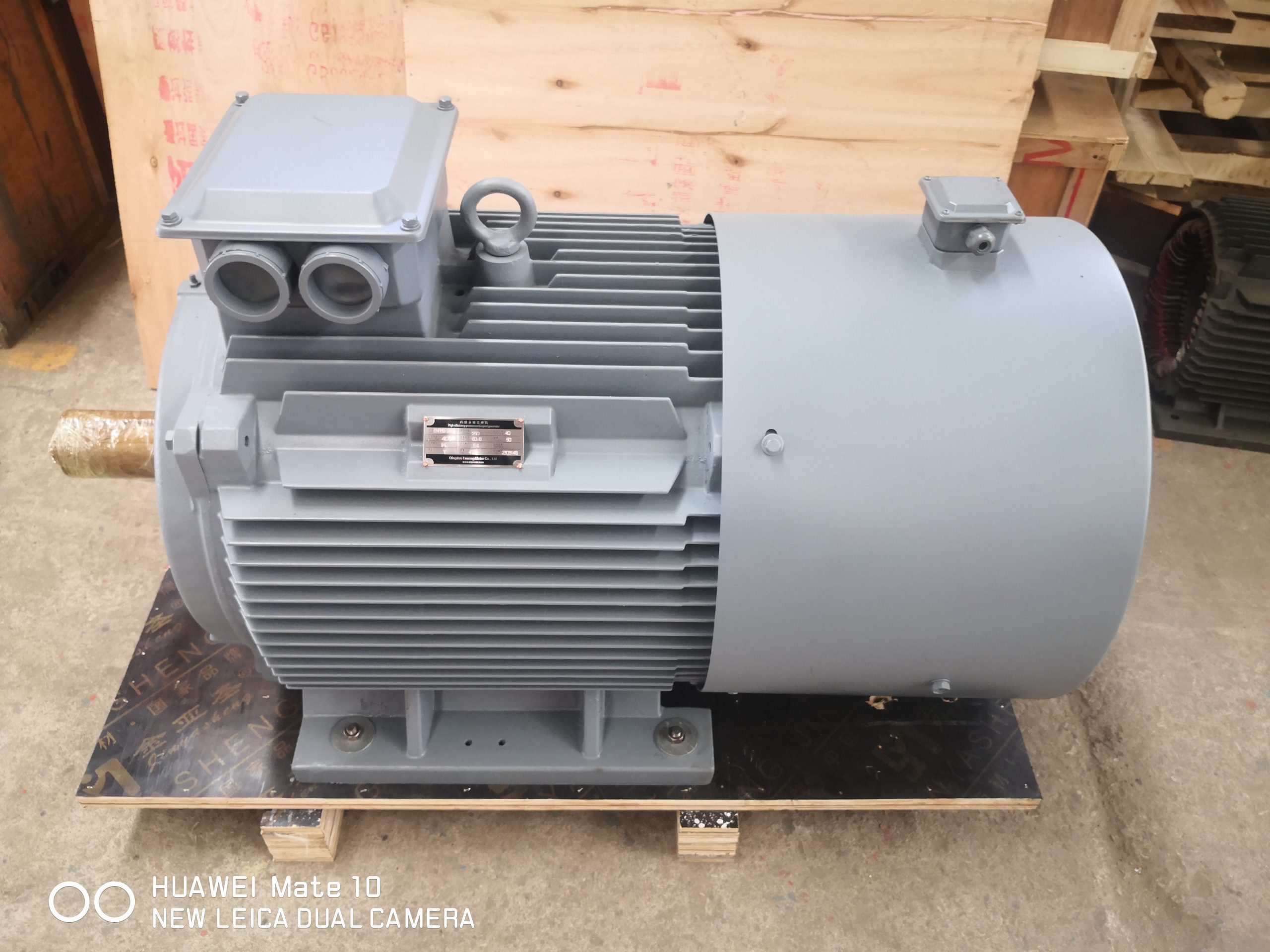
A large drum adds inertia to the page. Starting takes energy; stopping may send some back. If the process drives the motor during coast-down, the electrical sketch needs somewhere for that energy to go and a stop sequence everyone accepts.
Fewer wear parts may help here. A weak start envelope will not. The reviewer refuses one power number and asks for running torque, breakaway, peak duration, and available inverter current on separate lines.
Fans, cooling towers, and pumps emphasize the operating curve
A fan may visit maximum speed briefly and live elsewhere. Its speed distribution therefore goes beside the control method and minimum point. Reverse flow and windmilling get notes of their own. One rated dot cannot describe the year.
Cooling towers make the layout easy to picture: a slow motor can replace pieces of a conventional vertical chain when the design fits. Then the site intrudes. Heat, humidity, rain, water, corrosion, drainage, and access begin shaping enclosure and bearings.
Flow may keep a pump or fan turning after the command changes. Can the inverter catch that moving shaft? Will energy return? Direct drive answers the mechanical layout; the process still asks those control questions.
Mixers, extruders, and compressors emphasize process variation
The mixer card reads like a recipe. As viscosity moves, torque moves. Cleaning and empty running add different points. An average would erase the order, so time stays beside speed and torque.
The extruder trace is steadier until material or temperature changes. Then the requirement shifts. Coupling, torsional path, and process protection remain on the drawing even after the gearbox leaves it.
The compressor brings its own map. Minimum stable speed, pressure control, acceleration, stop, auxiliaries, and restart logic are already there; the motor cannot invent them. For all three machines, the process owner supplies the working range before direct drive earns a place on the shortlist.
Low-speed cooling is a design limit, not a footnote
At the slow point, the shaft fan is slow too. Full process torque may still be making heat. A review fixed on the rated dot can miss that mismatch entirely.
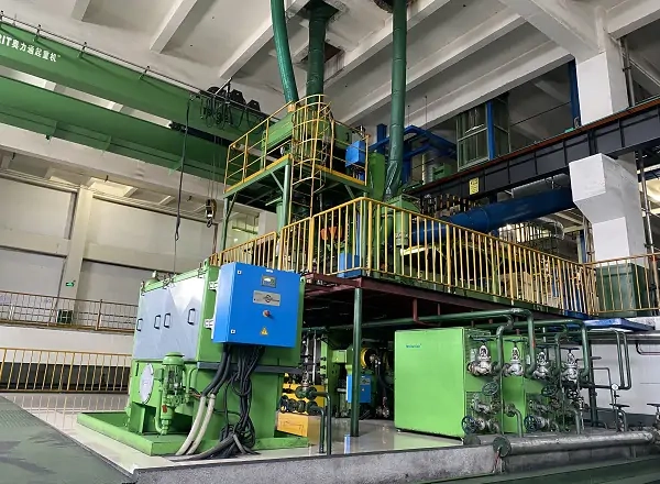
A separate blower breaks the link to shaft speed, then adds power, airflow proof, filters, and care. Water cooling brings its pump, exchanger, hoses, flow proof, drain, and site connections. The duty may need one of them. The label “direct drive” does not decide.
The supplier pins a thermal basis beside the continuous envelope. The plant pins temperature, altitude, dust, moisture, orientation, enclosure, and utilities beside that. One more question closes the loop: what does the controller do when the temperature signal rises? Without an action, the sensor only watches.
Feedback depends on the lowest-speed control task
Smooth running at mid-speed wins no argument about a loaded start. Nor does it prove standstill torque, quick reversal, or position. The hardest control corner decides whether sensorless operation is enough.
Where feedback is required, its resolution, mounting, connector, card, cable, shielding, replacement access, and failure response join the motor-drive package. Feedback direction and scaling are checked before loaded operation.
The inverter row begins with normal and peak current. Supply, filters, cable, ground, harmonics, communications, braking or regeneration, and parameter ownership follow. For a brownfield machine, the direct-drive retrofit checklist widens that review to the installation.
The main benefits have matching tradeoffs
Removing a gearbox can remove gears, oil, associated alignment, and some wear points. A shorter chain can reduce packaging length and transmission losses. Fewer components may simplify planned maintenance.
Flip the page. Low-speed torque can mean more diameter or mass. The cooler may have auxiliaries. A custom interface can tie the motor more tightly to one machine. Magnets need suitable handling and protection from damaging heat or electrical events. And if the rotor turns, maintenance has to account for generated voltage.
So there is no universal saving in the name. Count what the sketch removes, what it adds, how the process runs, and what installation will really take.
Selection ends with an interface and evidence package
The final folder opens with the torque-speed-time envelope and chosen layout. Behind them sit motor and inverter data, normal and peak limits, feedback, cooler, shaft or flange, bearing owner, load arrows, rotor inertia, protection, and site conditions.
Evidence follows the risk. The factory can check electrical characteristics, sensors, rotation, vibration, and the performance points its stand can reach. The assembled machine and missing process points wait for site. Drawings, data, parameters, reports, manuals, and spares keep one revision trail.
The ENNENG evidence stays narrow. ENNENG-CAND-006 and 008 record archived TYDP, gearless-family, and application context. ENNENG-CAND-010 records a customization statement. None proves fit, efficiency, savings, or compatibility here. Review the direct-drive product context, then send the operating envelope and interface drawings.
Evidence boundary
The ABB sources support general direct-drive PM architecture and motor-control context for their own products. They do not certify an ENNENG configuration. The admitted ENNENG records support only the limited historical statements above. Final selection depends on the offered motor-drive data, process map, mechanical interfaces, cooling and protection design, and agreed tests.