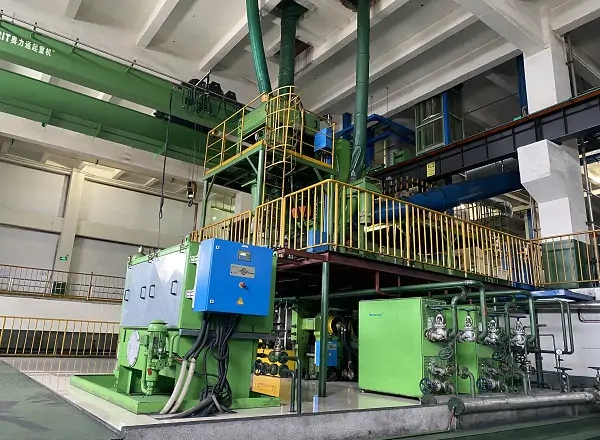
Extruder motor selection should begin with the screw and process, not with a motor efficiency label. An extruder may need strong torque at a cold or loaded start, steady screw speed while material properties change and thermal performance through long production runs. ENNENG's archived website shows a permanent magnet motor application for a tyre-factory compound extruder and a separate TYDP direct-drive family. Those records do not prove that the specific extruder example was gearless, or that one motor family fits every extrusion line. This guide helps process engineers build an evidence-based motor and drive specification without importing another plant's performance numbers.
Map the existing power path
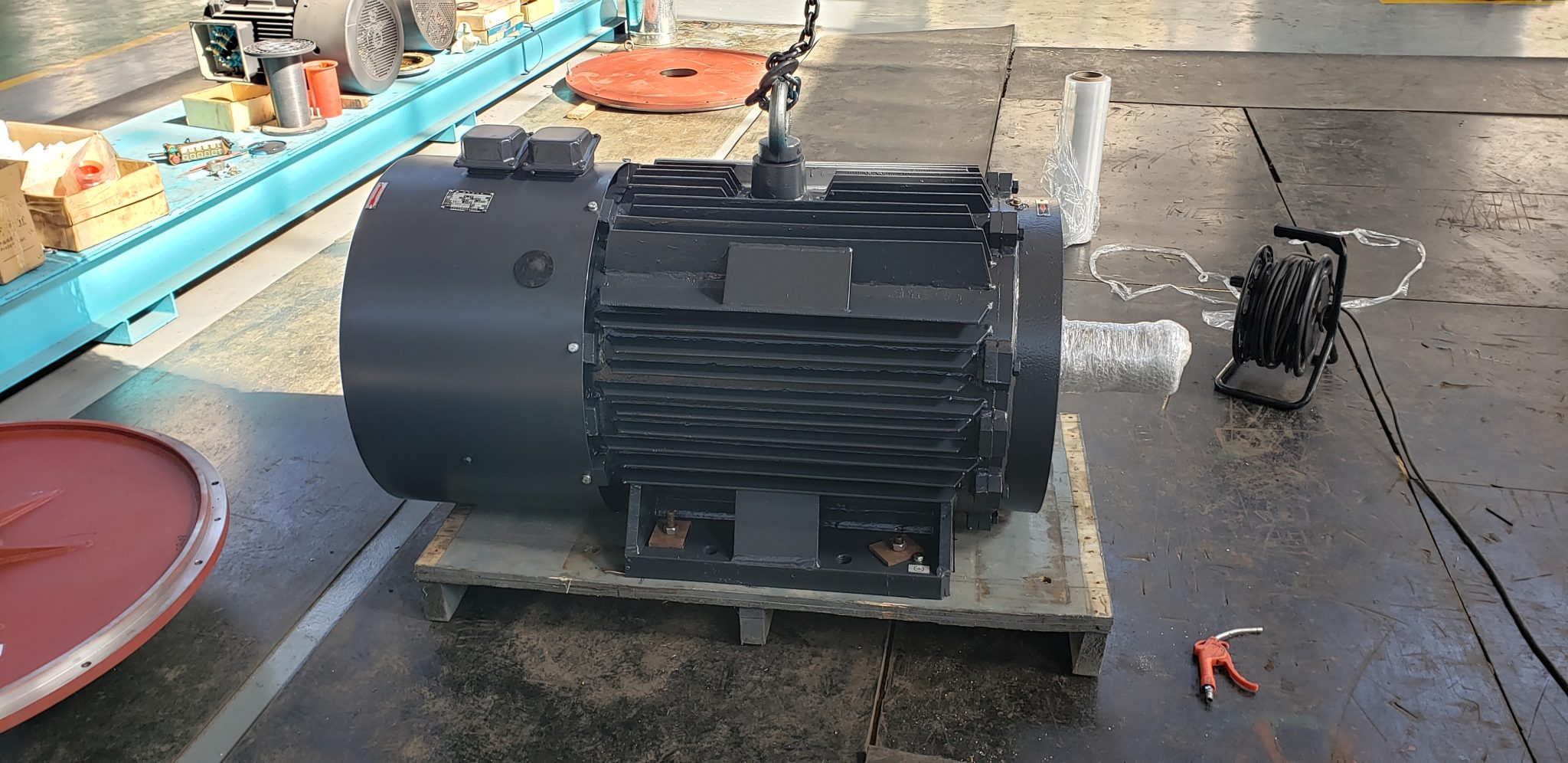
Draw the path from supply to converter, motor, coupling, reducer and screw. Mark the location of thrust bearings and any drive-shaft support. The gearbox may do more than reduce speed: it may carry screw thrust, provide an offset or support a maintenance arrangement. A direct-drive proposal needs a replacement for those functions or a justified reason they are not required. Record installed ratio, screw speed range, motor nameplate, drive settings, coupling and gearbox drawings, available installation space and the plant's preferred service access.
Take measurements before removing hardware. On representative recipes, capture screw speed, motor current or torque estimate, start time, barrel temperature, melt pressure and throughput. Identify instrument calibration and the recipe state associated with every trend. An extruder running one compound all day presents a different duty from a line that changes material and speed repeatedly. If the current drive lacks useful logging, a short controlled survey may be worth more than a speculative nameplate comparison. The direct-drive versus gearbox guide explains why the removed and retained components need to be specified together.
Separate starting torque from continuous process torque
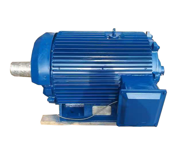
Cold material, a filled screw and static friction can make startup demanding. Running torque then varies with formulation, temperature, screw geometry and throughput. Define at least three states: a normal stabilized run, a representative high-load run and the permitted startup condition. Include duration and frequency. A brief torque peak cannot stand in for a continuous rating; a motor that survives one start may overheat during a long high-viscosity run. State the lowest continuous screw speed as well as the highest operating speed.
ABB's extruder guidance says its motor-drive pairing can deliver high starting torque and precise speed control for the equipment it sells. That is a useful example of the system questions to ask any supplier, not evidence of ENNENG capability at a specific operating point. Ask for the proposed motor's torque-speed curve with its drive, cooling and ambient assumptions. The low-speed high-torque sizing guide gives a broader method for translating those states into a specification. Do not insert a standard motor rating until the load envelope and interfaces are known.
Match speed control to product quality
Screw speed is one control variable in a process that also depends on feed, barrel heating, die condition and downstream equipment. A drive that holds speed accurately cannot compensate for every process upset. Still, it should respond predictably when material torque changes and coordinate with the line's start, stop and fault sequence. Define acceptable speed variation, ramp behavior and any requirements for closed-loop feedback with the process engineer. Confirm how speed and torque limits are communicated to the supervisory controller and displayed to operators.
During commissioning, log screw speed beside melt pressure and throughput, rather than judging the drive from motor current alone. If product defects appear, compare process conditions before retuning the motor. Keep separate versions of recipes and drive parameters so a later change can be traced. The motor supplier, converter integrator and machine OEM should agree who owns the final control loop. Without that assignment, a speed disturbance can be blamed on the wrong component and the fix may simply mask a feed or temperature problem.
Check thermal duty at the lowest production speed
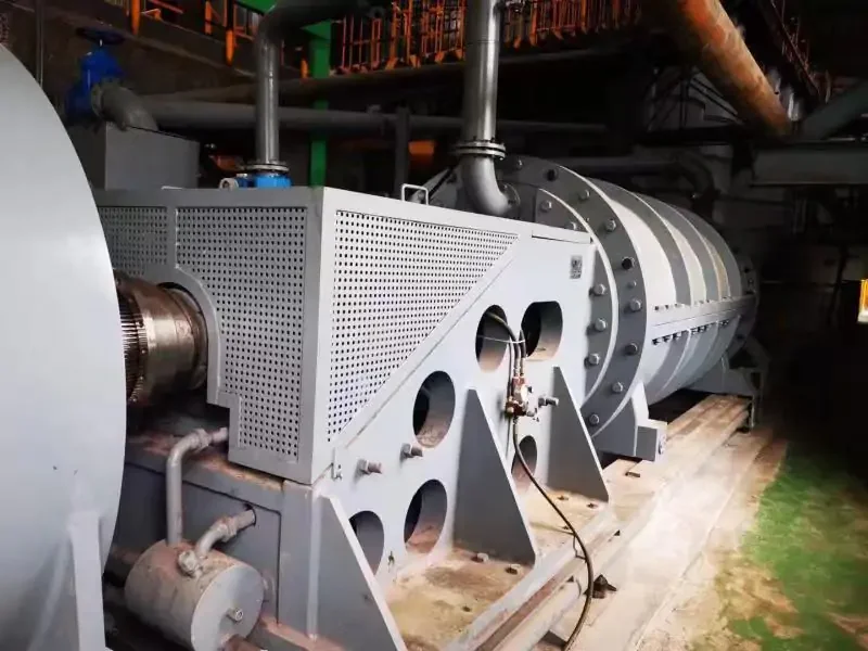
Extruders often run for long periods. At low speed, a shaft-mounted fan may provide less cooling even while the motor produces substantial torque. Ask for continuous torque capability at the actual speed and ambient temperature, not just a broad power rating. Document cooling air or water supply, filter maintenance, sensor positions and protective trip logic. Where a separate fan or liquid system is proposed, include its electrical load and failure behavior in the package evaluation. A low-speed concept should be judged in its worst sustained process condition.
Bearings and insulation also matter when a converter is introduced or changed. ABB's extruder material discusses temperature monitoring and bearing measures in its own motor range. Treat these as prompts for the specification: what are the bearing current controls, cable and grounding requirements, winding insulation assumptions and monitoring points for the proposed package? Obtain model-specific answers. The presence of a permanent magnet rotor does not make the entire line maintenance-free. Scheduled checks remain for bearings, cooling, connections, sensors and the mechanical interface.
Study direct drive without assuming it wins
Removing the reducer can eliminate some losses, lubrication tasks and alignment points, but a direct-coupled motor must produce the required screw torque at screw speed and fit beside the machine. Its size, mass and torque reaction can change the base and guarding. The extruder may still need a thrust-bearing housing. Compare at least two complete arrangements: a motor-and-reducer replacement and a direct-drive package with its converter, support and cooling. Use the same output requirement and duty cycle for both. The apparent component count tells only part of the story.
ENNENG's TYDP page identifies a low-speed permanent magnet direct-drive family, while its older compound-extruder page identifies a motor application. The archive does not establish that the tyre-factory motor was TYDP or that the photographed system eliminated gearing. Avoid placing those claims in a proposal without a matching drawing or test record. The TYDP overview can frame a separate feasibility discussion. For a given extruder, the decision should be based on an as-built interface survey and a supplier-specific performance offer.
Compare energy on the same production basis
Metering only the motor input before and after a retrofit can mislead if throughput, product formulation or cooling loads change. Define a boundary that includes the motor, converter and relevant auxiliaries; then record energy per comparable production output under documented recipes. Capture hours at each operating point because efficiency at the rated point may not represent the duty. Where the old gearbox loss is estimated, show the source and uncertainty. Do not convert a generic product-page efficiency claim into a plant payback estimate.
The US Department of Energy's motor-systems resources emphasize system management and measurement. Apply that discipline here. Calculate energy cost separately from maintenance labor, spares, quality loss and shutdown risk. If a supplier predicts a saving, require the input assumptions and a site acceptance method. ENNENG's old extruder material is evidence of a company-described application, but it does not provide a transferable measured saving for a new line. A cautious comparison may find that improved control is the main value, or that a simpler motor-and-drive upgrade meets the target.
Plan the installation and acceptance tests
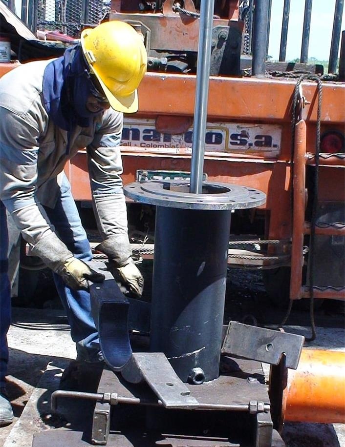
An extruder retrofit intersects production, electrical safety and machine mechanics. Survey the base and lifting route, cable paths, converter cabinet, cooling connection, shaft alignment and access to the screw assembly. Freeze the interface drawings before shutdown. Write a rollback plan for critical lines. Commission protection and rotation checks first; then run a controlled startup, low-speed stabilization, representative recipe changes and a sustained high-load condition that the plant can safely reproduce. Record process state alongside current, speed, temperature and alarms.
Acceptance should specify the exact recipe or material family, throughput range, product quality checks, measurement instruments and stabilization period. Some conditions cannot be reproduced on the first day; identify a later witnessed trial instead of declaring them passed. Handover should include as-built drawings, drive parameter backup, motor thermal limits, maintenance tasks and spare-parts list. This makes a future fault actionable for the plant team. The selection guide offers an RFQ checklist, and the inquiry form provides a route to send the operating data for technical review.
Technical references and evidence boundary
- ABB: Reliable performance pairing for extruder OEMs discusses starting torque, speed control and monitoring for ABB's motor-drive packages.
- US Department of Energy Motor Systems provides system-level assessment resources.
- ENNENG knowledge archive: ENNENG-SRC-FB967A2ECBFAEA204AAF, Compound Extruder of Tyre Factory; ENNENG-SRC-A7BE842A124937682FBA, The Application of Permanent Magnet Motor in Rubber Extruder; ENNENG-SRC-FA10C0DAACC73B5A100C, TYDP Series Direct Drive and Gearless Motor. These company-source records must not be interpreted as a verified performance test for this guide.
Bring the operating data to the discussion.
Selection depends on the actual load, drivetrain and site constraints. Share your measurements and drawings for a project-specific review.